Table of Contents
A draftsperson can fix a thin line. Nobody can fix a view you never drew. That is why patent drawings for mechanical inventions get objected to for different reasons than chemical or software figures do: the linework is usually fine, and the problem is that the claim recites an internal cam surface, a bearing seat or an order of assembly that no figure in the application actually shows. By the time the examiner says so, the only cure is a replacement sheet, and the only safe replacement sheet is one that adds nothing new. The eight checks below are the ones we run on a mechanical figure set before it goes anywhere near a filing receipt.
Why Patent Drawings for Mechanical Inventions Fail on Views, Not Linework
Mechanical inventions are three-dimensional, assembled, and usually hollow somewhere. A pump, a hinge, a gearbox or a surgical stapler has surfaces that matter and that cannot be seen from outside. Chemical figures are flat; software figures are flowcharts. Mechanical figures have to carry depth, and depth is what the drawing rules police hardest.
The governing standard is 37 CFR 1.84, “Standards for drawings.” Most practitioners know subparagraphs (f), (g) and (l) — sheet size, margins and line quality — because those are the ones a formality review flags mechanically. Paragraph (h) is the one that decides whether a mechanical application is actually enabled by its figures, and it is the one most commonly left to the illustrator.
Paragraph (h) has five subparagraphs, and each maps to a situation a mechanical inventor runs into constantly:
- (h)(1) Exploded views — the order of assembly
- (h)(2) Partial views — machines too large for one sheet
- (h)(3) Sectional views — everything you cannot see from outside
- (h)(4) Alternate position — moving parts
- (h)(5) Modified forms — alternative embodiments
Run paragraph (h) as a five-way checklist against your claim set and most mechanical drawing objections disappear before they are written. Our guide to patent drawing views covers the underlying view types; this article is about which of them a mechanical claim set forces you to include.
Check 1: Every Claimed Feature Has to Appear Somewhere
37 CFR 1.83(a) is short and unforgiving: the drawing in a nonprovisional application must show every feature of the invention specified in the claims. Not the gist of the feature — the feature. If claim 1 recites “a tapered bore having a shoulder,” a figure has to show the taper and the shoulder.
The practical method is mechanical, not artistic. Print the claim set. Highlight every structural noun and every relational phrase — engages, seated within, coaxial with, spaced apart from. Then write a figure number next to each one. Any highlight without a figure number is a drawing objection waiting to happen, and often a 35 U.S.C. 112 problem sitting behind it.
This is where patent drawings for mechanical inventions diverge sharply from other art. A relational phrase in a mechanical claim is nearly always an internal relationship, and an internal relationship nearly always needs a section. That single inference — relational limitation implies sectional view — catches more problems than any line-weight audit.
Do the exercise before the figures are drawn, not after. Adding a view to a pending application means a replacement sheet under 37 CFR 1.121(d), and anything in that new view that was not already disclosed is new matter. Our note on amending patent drawings explains why that door closes so quickly.
Check 2: Sectional Views and the Hatching Rule in 1.84(h)(3)

Paragraph (h)(3) is the single most load-bearing rule in mechanical drafting, and it is specific. Hatching must be used to indicate section portions of an object, and must be made by regularly spaced oblique parallel lines spaced sufficiently apart to enable the lines to be distinguished without difficulty. The spacing is chosen on the basis of the total area to be hatched.
Then comes the angle requirement: hatching must be at a substantial angle to the surrounding axes or principal lines, preferably 45°. The reason is legibility, not aesthetics. Hatching drawn parallel to a part’s own axis reads as surface texture rather than a cut face, and at publication reduction it disappears into the outline entirely.
Three consequences follow for an assembled mechanical device:
- Adjacent parts must be hatched differently. The hatching of juxtaposed different elements has to be angled in a different way, otherwise two mating components read as one solid block — fatal when the claim depends on them being separate.
- Hatching must not bury the reference characters. Numerals and lead lines have to stay legible through the hatch. In a dense gearbox section this usually means wider spacing, not smaller numerals.
- The cut has to be traceable. The sectional view must correspond to the view it was taken from, with the cutting plane indicated by a broken line and arrows showing the direction of sight.
The failure mode we see most often is a section drawn from a plane that the parent view never marks. The figure is beautiful and the examiner cannot tell where it came from. Our deep dive on patent drawing sectional views works through the cutting-plane conventions in detail.
Check 3: Exploded Views Need a Bracket, Not Just Separation
Paragraph (h)(1) permits exploded views, with the separated parts embraced by a bracket, to show the relationship or order of assembly of various parts. Read that carefully: the bracket is part of the permission, not decoration. An exploded cluster floating unbracketed on a sheet alongside other figures is ambiguous — the examiner cannot tell whether the separated items are one exploded assembly or several independent figures.
Exploded views are the natural answer to any claim that recites an order, a sequence of assembly, or a stack. If your claim says “a washer interposed between the flange and the housing,” an exploded view proves the interposition more cleanly than three separate section cuts ever will.
Two drafting habits keep exploded figures out of trouble. First, keep the explosion on a single axis wherever possible, so the order of assembly reads left-to-right or bottom-to-top without the reader reconstructing it. Second, carry the same reference numeral for a part into every view it appears in — a bolt that is 42 in the assembly and 42a in the exploded view invites an objection for inconsistent reference characters.
Note the interaction with paragraph (i): one view must not be placed upon another or within the outline of another. A crowded exploded view that overlaps the assembled figure breaks (i) even though it satisfies (h)(1).
Check 4: Partial Views of Machines Too Large for One Sheet
Paragraph (h)(2) handles the case mechanical practitioners hit and software practitioners never do: the device does not fit. When necessary, a view of a large machine or device in its entirety may be broken into partial views on a single sheet, or extended over several sheets, if there is no loss in facility of understanding the view.
Two conditions attach. Where the partial views are extended over several sheets, they must be arranged so the complete figure can be assembled without concealing any part of any view. And a smaller-scale view of the whole, with the positions of the parts indicated, should be included so the reader knows how the pieces fit.
In practice this is the difference between a conveyor system that reads as one machine and one that reads as four unrelated fragments. The small key view is the cheapest insurance in the whole figure set, and it is the element most often omitted.
Resist the temptation to solve a size problem by shrinking the scale instead. 37 CFR 1.84(k) requires the scale to be large enough to show the mechanism without crowding when the drawing is reduced to two-thirds in reproduction — so a scale chosen to fit the sheet will often fail the reduction test. Breaking the view is the sanctioned answer; shrinking it is not.
Check 5: Moving Parts, Alternate Positions and Modified Forms
Mechanical claims move. Hinges open, pistons travel, jaws close — and the figures have to show both states without creating a second invention. Paragraph (h)(4) sets the rule: a moved position may be shown by a broken line superimposed upon a suitable view if this can be done without crowding; otherwise, a separate view must be used for that purpose.
The “without crowding” qualifier is doing real work. A broken-line overlay on a simple two-position lever is clear. The same overlay on a multi-link mechanism produces a thicket in which the examiner cannot tell which broken line belongs to which element. When in doubt, draw the second position as its own figure — an extra sheet costs far less than an office action.
Paragraph (h)(5) is blunter: modified forms of construction must be shown in separate views. If the specification describes an alternative embodiment — a threaded version and a bayonet version of the same coupling — they cannot share a figure with broken lines distinguishing them. Each gets its own view.
Watch the broken-line budget. In a utility application broken lines carry several different meanings at once: hidden structure, moved positions under (h)(4), and the boundary of a partial view. If all three appear in one figure with the same line style, the drawing becomes genuinely ambiguous, and the examiner is entitled to say so.
Check 6: Surface Shading That Survives Publication Reduction
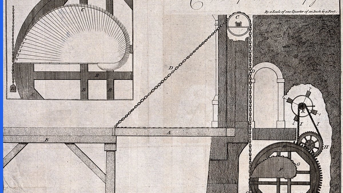
Paragraph (m) encourages shading where it aids understanding and does not reduce legibility, and it specifically contemplates the mechanical case: shading is used to indicate the surface or shape of spherical, cylindrical and conical elements. A shaft, a boss, a dome or a tapered nozzle reads as a flat silhouette without it.
The rule then constrains how. Spaced lines for shading are preferred; those lines must be thin, as few in number as practicable, and must contrast with the rest of the drawing. Light should come from the upper left corner at an angle of 45°. Solid black shading areas are not permitted, except when used to represent bar graphs or colour.
That last sentence is the one that catches CAD-exported figures. A renderer’s default ambient-occlusion pass produces exactly the solid black gradient the rule forbids, and it produces it on the surfaces a mechanical claim cares about most. Converting a solid render to compliant line shading is manual work, which is why engineering CAD rarely survives contact with 1.84 untouched.
Shading also has to clear paragraph (l): every line, number and letter must be durable, clean, black, sufficiently dense and dark, and uniformly thick and well-defined. A shading line thin enough to look elegant on screen can drop below reproducible density once the sheet is reduced. We cover the thresholds in our note on patent drawing shading requirements.
One number worth committing to memory, because it governs everything you letter onto a mechanical sheet: under 37 CFR 1.84(p)(3), numbers, letters and reference characters must measure at least 0.32 cm (1/8 inch) in height.
Check 7: The Same Mechanical Set at the EPO and Under the PCT
A mechanical figure set almost always travels, and patent drawings for mechanical inventions are judged against a different instrument in Europe than in the United States. Getting the European position right matters, and the law here changed recently enough that a great deal of published guidance is now wrong.
Rule 46 EPC no longer exists. Rule 46 EPC, which set the form of the drawings, was deleted with effect from 1 February 2023, together with Rule 49(3) to (12) EPC, as part of the EPO’s digital-transformation package; Rules 49(2), 50, 57(i) and 82(2) EPC were adapted to match. Any page still telling you your figures must be “Rule 46 EPC compliant” is citing a rule that has not been in force for over three years.
Rule 49(2) EPC now leaves the presentation of the application documents to the President of the EPO, so the drawing form requirements live in a Decision of the President published in the Official Journal. For documents filed on or after 1 October 2025 that is the decision at OJ EPO 2025, A49, which replaced the decision at OJ EPO 2022, A113. Since 1 October 2025 the EPO accepts drawings filed electronically in colour or greyscale, provided they are contrast-rich and clear, and processes them through to publication without conversion to black and white.
The PCT did not change. PCT Rule 11.13 still requires drawings to be executed in durable, black, sufficiently dense and dark, uniformly thick and well-defined lines and strokes without colourings. So a colour sectional view that is now perfectly filable at the EPO is still non-compliant for an international application. For a mechanical set destined for both, draft in compliant line shading and treat colour as an EPO-only option rather than the master format.
The practical upshot: build one master set that satisfies the strictest constraint in each dimension — A4 sheets, 0.32 cm lettering, black line shading, no solid fills — and it will clear the USPTO, the EPO and the International Bureau without a redraw. Our USPTO versus EPO comparison sets the two regimes side by side.
Check 8: If It Is a Design Filing, 1.152 Reverses Two Rules
Mechanical inventors frequently file a utility application and a design application on the same product, and assume one figure set can serve both. It cannot, because 37 CFR 1.152 changes the meaning of two things a mechanical draftsperson relies on.
Under 1.152, the design must be represented by a drawing that complies with 37 CFR 1.84 and must contain a sufficient number of views to constitute a complete disclosure of the appearance of the design. Appropriate and adequate surface shading should be used to show the character or contour of the surfaces represented — in a design case shading is not merely encouraged, it is how contour is claimed. Solid black surface shading remains impermissible except to represent the colour black or colour contrast.
Then the two reversals. Broken lines may be used to show visible environmental structure, but may not be used to show hidden planes and surfaces that cannot be seen through opaque materials — the exact opposite of their primary utility use. And alternate positions of a design component illustrated by full and broken lines in the same view are not permitted, which removes the paragraph (h)(4) overlay a utility draftsperson would reach for first.
So the hidden-detail section views and the moving-part overlays that make a good utility set are affirmatively wrong in the design case. Treat them as two sets from the outset. Our walkthrough of 37 CFR 1.152 covers the design side on its own terms.
A Pre-Filing Checklist for Mechanical Figure Sets
Run this before the figures leave your desk. It takes about twenty minutes on a ten-sheet set and it is the review that makes patent drawings for mechanical inventions clear formalities on the first pass.
- Every structural and relational limitation in the claims is traceable to a numbered figure (1.83(a)).
- Each internal relationship has a sectional view, and each section’s cutting plane is marked on its parent view with direction-of-sight arrows.
- Hatching is oblique, regularly spaced, at a substantial angle — preferably 45° — and differently angled for juxtaposed parts (1.84(h)(3)).
- Reference characters and lead lines remain legible through every hatched region.
- Exploded clusters are embraced by a bracket (1.84(h)(1)) and no view overlaps another (1.84(i)).
- Partial views reassemble without concealment, and a small whole-device key view is present (1.84(h)(2)).
- Moved positions are broken-line overlays only where uncrowded; alternative embodiments have separate views (1.84(h)(4), (h)(5)).
- Surface shading is spaced thin lines, light from the upper left at 45°, with no solid black fills (1.84(m)).
- Lettering is at least 0.32 cm high and numerals are consistent across every view (1.84(p)(3)).
- Sheets are a single size, A4 or 21.6 by 27.9 cm, with top and left margins of at least 2.5 cm, right at least 1.5 cm, bottom at least 1.0 cm (1.84(f), (g)).
If the same set is going abroad, add two lines: no colour if the PCT is in the route, and no reliance on Rule 46 EPC in any instruction you send a European associate.
Have Your Mechanical Figures Reviewed Before You File
PerspireIP prepares and reviews mechanical figure sets against 37 CFR 1.84 and 1.152, the current EPO standards and PCT Rule 11.13 — sectional views with compliant hatching, bracketed exploded assemblies, partial views that reassemble, and line shading that survives publication reduction. If you have a claim set and a CAD model, we will tell you which views are missing before an examiner does. See our patent drawing services or talk to us about a figure set.
Frequently Asked Questions
How many views does a mechanical patent application need?
There is no minimum count. Patent drawings for mechanical inventions need as many views as it takes to show every feature recited in the claims, which is what 37 CFR 1.83(a) requires. In practice an assembled mechanical device needs at least one perspective or elevation view for context, one sectional view per internal relationship claimed, and an exploded view wherever the claim recites an order of assembly.
What angle should hatching be in a sectional view?
37 CFR 1.84(h)(3) requires hatching to be at a substantial angle to the surrounding axes or principal lines, preferably 45 degrees. Juxtaposed different elements must be hatched at different angles so that mating parts do not read as a single solid body.
Can I use a CAD render as a patent drawing?
Not without conversion. A shaded render almost always contains solid black shading areas, which 37 CFR 1.84(m) does not permit, and grey gradients that fail the density requirement in 1.84(l). The geometry is reusable; the rendering is not. Compliant figures use thin spaced lines for shading with light from the upper left at 45 degrees.
Do EPO drawings still have to comply with Rule 46 EPC?
No. Rule 46 EPC was deleted with effect from 1 February 2023. The form requirements now sit in a Decision of the President of the EPO under Rule 49(2) EPC; for documents filed on or after 1 October 2025 that is the decision at OJ EPO 2025, A49, and colour or greyscale drawings filed electronically are accepted.
Can one figure set cover both a utility and a design filing?
No. 37 CFR 1.152 reverses two conventions: broken lines may show visible environmental structure but not hidden planes, and alternate positions shown by full and broken lines in one view are not permitted. The hidden-detail sections and moving-part overlays that make a good utility set are affirmatively wrong in a design application.
Does a colour sectional view work for a PCT application?
No. PCT Rule 11.13 still requires lines and strokes without colourings, and it was not changed when the EPO began accepting colour on 1 October 2025. If an international application is in the route, keep the master set in compliant black line work and treat colour as an EPO-only variant.