Table of Contents
A cut-away tells the examiner what an exterior view never can — which part is solid, which is hollow, and what each piece is made of. That is why patent drawing sectional views carry more formal requirements than any other view type in the rulebook. Section 1.84(h)(3) of Title 37 is one dense paragraph, and almost every objection in this area traces back to three lines of it: how the cutting plane is marked, how the hatching is angled, and whether the section really shows the materials it should. Get those wrong and you get a drawing objection in the first Office action — rarely fatal, always a delay.
What Patent Drawing Sectional Views Must Actually Show
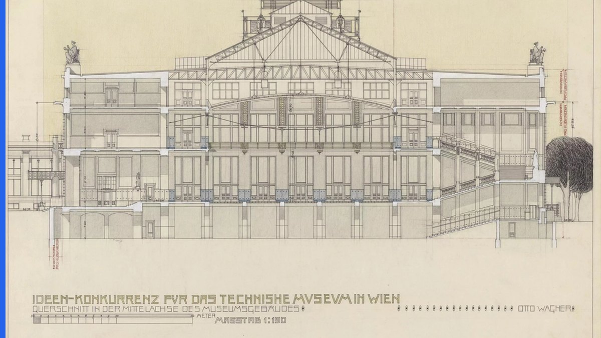
Rule 1.84(h) opens by telling you what kinds of views are available: “The views may be plan, elevation, section, or perspective views.” A section is therefore a first-class view, not an optional extra, and it is judged against the same standards of line quality and legibility as everything else on the sheet.
The substantive requirement is easy to state and easy to violate. The rule says: “A cross section must be set out and drawn to show all of the materials as they are shown in the view from which the cross section was taken.” In other words, the section is not a free-standing sketch. It is a derived view, and it has to be internally consistent with its parent.
This is where a surprising number of applications come unstuck. A draftsperson redraws the section from the inventor’s CAD model rather than from the elevation view already on the sheet, and the two disagree — a boss appears in one and not the other, or a wall thickness changes. An examiner comparing the two views will object, and because the drawings are part of the disclosure, correcting the mismatch after filing can raise a new-matter question rather than a simple formality.
- Every element cut by the plane must appear in the section — nothing silently omitted.
- Nothing may appear in the section that is absent from the parent view.
- Wall thicknesses, bores and fillets must match the view the plane was taken from.
- The section must show materials, not just outlines — hatching is how you do that.
If you are still deciding which views your application needs at all, our guide to patent drawing views covers the full set — plan, elevation, perspective, detail and exploded — and when each earns its place on the sheet.
Marking the Cutting Plane: Broken Lines, Numerals and Arrows
The first half of 1.84(h)(3) is about orientation — telling the reader where the cut was made and which way the viewer is looking. The rule is specific: “The plane upon which a sectional view is taken should be indicated on the view from which the section is cut by a broken line. The ends of the broken line should be designated by Arabic or Roman numerals corresponding to the view number of the sectional view, and should have arrows to indicate the direction of sight.”
Three separate obligations are bundled into that sentence, and applicants routinely satisfy one or two of them:
- A broken line on the parent view showing exactly where the plane passes. It goes on the view being cut, not on the section itself.
- Numerals at both ends of that line that correspond to the figure number of the sectional view. If the section is FIG. 3, the cut-plane line is labelled 3–3. Arabic or Roman are both acceptable, but be consistent across the application.
- Arrows showing the direction of sight. Without them the reader cannot tell which half of the object was discarded, and a symmetrical part becomes ambiguous.
Note the drafting: the rule uses “should” for the cut-plane conventions and “must” for hatching. That distinction matters in practice. A missing arrow is usually met with an objection and an invitation to correct; hatching that is absent altogether is a harder problem because the section is then failing to convey material at all.
The numerals on the cut-plane line are reference characters, so they inherit the lettering standards in 1.84(p) — the same discipline you apply to every other callout. Our post on patent drawing reference numerals works through the numbering conventions that keep a multi-sheet application coherent.
Hatching Angle and Spacing — the 45° Default
Hatching is the part of the rule written in mandatory language: “Hatching must be used to indicate section portions of an object, and must be made by regularly spaced oblique parallel lines spaced sufficiently apart to enable the lines to be distinguished without difficulty.”
Then comes the angle requirement that most objections cite: “Hatching must be at a substantial angle to the surrounding axes or principal lines, preferably 45°.” Read that carefully — 45° is a preference, not a mandate. The mandate is the substantial angle relative to the surrounding geometry. A part whose principal lines already run at 45° should not be hatched at 45°, because the hatching would then be parallel to the outline and the section would read as a solid smear.
Spacing is governed by reproduction, not aesthetics. The rule ties the interval to area: “the space between strokes being chosen on the basis of the total area to be hatched.” A large area tolerates wider spacing; a narrow web needs tighter lines or it will read as empty. Because 1.84(k) requires the drawing to survive reduction to two-thirds in reproduction, hatching that looks crisp at 100% and fills in at 67% is non-compliant even though it looked fine on your monitor.
There is a genuine relief valve for very large areas: “In the case of large areas, hatching may be confined to an edging drawn around the entire inside of the outline of the area to be hatched.” That is a legitimate way to keep a big casting from turning into an unreadable block of lines.
Line weight in patent drawing sectional views is explicitly covered too. Rule 1.84(l) requires every line to be durable, clean, black, sufficiently dense and dark, and uniformly thick — and adds that the requirement “applies to all lines however fine, to shading, and to lines representing cut surfaces in sectional views.” Hatching is not exempt from line-quality standards because it is thin. See our breakdown of patent drawing line thickness for the practical numbers.
Hatching Juxtaposed Parts and Conventional Material Meanings
Once more than one component is cut by the same plane, hatching stops being decoration and starts doing legal work — it is what tells the reader where one part ends and the next begins. The rule is direct: “The hatching of juxtaposed different elements must be angled in a different way.”
Its companion requirement is equally important and more often missed: “The various parts of a cross section of the same item should be hatched in the same manner and should accurately and graphically indicate the nature of the material(s) that is illustrated in cross section.” So a single component cut in two places by the same plane keeps one hatching style throughout, while the part bolted next to it must differ.
- Same part, multiple cut regions → identical hatch angle and spacing.
- Adjacent different parts → visibly different angle (commonly mirrored, or 45° against 135°).
- Three or more adjacent parts → vary spacing as well as angle; two angles will not carry four components.
- Thin parts such as gaskets or shims → these are the ones that fill in at reduced scale; widen the spacing.
The rule also permits a material vocabulary: “Different types of hatching should have different conventional meanings as regards the nature of a material seen in cross section.” This is the basis for the familiar symbol set — dots for a non-metallic solid, alternating long and short strokes for insulation, and so on. Using it is optional; using it inconsistently is what draws an objection, because the same pattern then means two things in one application.
One practical point on reference characters: “Hatching should not impede the clear reading of the reference characters and lead lines. If it is not possible to place reference characters outside the hatched area, the hatching may be broken off wherever reference characters are inserted.” Breaking the hatching around a numeral is expressly permitted — you do not have to choose between a legible callout and a compliant section.
Where Sectional Views and Shading Under 1.84(m) Collide
Shading and hatching are different things that look superficially alike, and conflating them is a recurring source of rework. Rule 1.84(m) encourages shading — “The use of shading in views is encouraged if it aids in understanding the invention and if it does not reduce legibility” — and explains that it “is used to indicate the surface or shape of spherical, cylindrical, and conical elements of an object.”
But it then carves out an explicit exception that governs patent drawing sectional views: shading “is preferred in the case of parts shown in perspective, but not for cross sections. See paragraph (h)(3) of this section.” The rule itself points you back at the hatching paragraph. Surface shading belongs on the perspective view; the cut face gets hatching, and adding contour shading on top of hatching reduces legibility and invites an objection.
Rule 1.84(m) also bans one tempting shortcut outright: “Solid black shading areas are not permitted, except when used to represent bar graphs or color.” Filling a thin cut section with solid black because the hatching would not resolve is therefore not an option — the correct fix is wider spacing or the edging technique from (h)(3).
We cover the surface-shading side of this boundary in detail in our guide to patent drawing shading requirements, which is worth reading alongside this one if your application mixes perspective and section views on the same sheet.
Sectional Views in Design Applications Under 37 CFR 1.152
Design applications import the utility drawing standards and then add their own. Rule 1.152 begins: “The design must be represented by a drawing that complies with the requirements of § 1.84 and must contain a sufficient number of views to constitute a complete disclosure of the appearance of the design.” So 1.84(h)(3) applies to a design section as well.
The overlay changes the emphasis, because a design claim covers appearance rather than structure. Rule 1.152 requires that “appropriate and adequate surface shading should be used to show the character or contour of the surfaces represented,” and provides that “solid black surface shading is not permitted except when used to represent the color black as well as color contrast.”
Two design-specific traps are worth naming. First, broken lines mean something different here: under 1.152 they “may be used to show visible environmental structure, but may not be used to show hidden planes and surfaces that cannot be seen through opaque materials.” A cut-plane line is a drafting convention, but a stray broken line elsewhere in a design drawing carries claim-scope consequences. Second, 1.152 states that “alternate positions of a design component, illustrated by full and broken lines in the same view are not permitted in a design drawing” — which is the opposite of the utility practice in 1.84(h)(4), where “a moved position may be shown by a broken line superimposed upon a suitable view.”
Because a design section is often used to show a contour that no exterior view captures, think hard about whether you need one at all: every view you add is part of what the design claim discloses. Our comparison of utility versus design patent drawings sets out the wider differences.
Cross-Sections at the EPO — and Why Rule 46 EPC No Longer Applies
If you are taking the same drawings to Europe, one piece of housekeeping matters more than the technical differences: Rule 46 EPC, “Form of the drawings,” has been deleted. It was removed by Administrative Council decision CA/D 10/22, in force from 1 February 2023, and the EPO’s own publication of the Implementing Regulations now renders the provision simply as “Rule 46 – (deleted).” A great many drawing guides — and more than a few live law-firm pages — still cite it as though it were current.
The requirements did not disappear; they moved. The EPO applies the presentation requirements for application documents through Rule 49 EPC and works them out in the Guidelines for Examination, Part A, Chapter IX. If you are citing a European drawing requirement today, cite the Guidelines, not Rule 46.
On substance the EPO is close to the USPTO but not identical. Guidelines A-IX, 7.3.2 (“Hatching”) provides that “a cross-section must be set out and drawn in the same manner as a normal view whose parts in cross-section are hatched with regularly spaced strokes, the space between strokes being chosen on the basis of the total area to be hatched,” and carries the same caution that hatching should not impede the clear reading of the reference signs and leading lines, and may be broken off where references are inserted.
The PCT sets the floor for anything entering the international phase. PCT Rule 11.13(b) states that “cross-sections shall be indicated by oblique hatching which should not impede the clear reading of the reference signs and leading lines” — note “oblique,” which rules out hatching parallel to the sheet edges. Our guides to the EPO Guidelines A-IX on drawings and to PCT drawing requirements go through the rest of the divergence.
A set of sections drawn to 1.84(h)(3) will generally satisfy the EPO and the PCT, because the American rule is the stricter of the three on cut-plane labelling. The reverse is not reliably true.
7 Rules Examiners Enforce on Patent Drawing Sectional Views
Distilled from the text of the rules, here is the checklist we run every section through before an application goes out the door:
- Mark the plane on the parent view with a broken line — not on the section itself.
- Label both ends with numerals matching the section’s figure number, Arabic or Roman, used consistently throughout the application.
- Add direction-of-sight arrows. A section without arrows is ambiguous on any symmetrical part.
- Hatch every cut region with regularly spaced oblique parallel lines — “must,” not “should.”
- Angle the hatching substantially away from the surrounding principal lines, 45° by preference, and give adjacent different parts different angles.
- Keep one hatch style per component, and make any material-convention patterns mean the same thing on every sheet.
- Reconcile the section against its parent view so that it shows all of the materials as they appear in the view it was taken from.
Two failure modes account for most of the objections we see. The first is the section that was never checked against reduction — hatching that closes up at two-thirds scale, which 1.84(k) requires the drawing to survive. The second is the redrawn section that quietly disagrees with its parent view, which is the one that can turn a formality into a new-matter argument. Both are cheap to catch before filing and expensive to fix afterwards.
Drawing objections are ordinarily raised in the first Office action or through a Notice to File Corrected Application Papers, and are answered with replacement sheets. For the mechanics of doing that without introducing new matter, see amending patent drawings and our catalogue of patent drawing mistakes that trigger Office actions.
Get Your Sectional Views Right the First Time
PerspireIP’s draftspeople prepare patent drawing sectional views to 37 CFR 1.84(h)(3), 37 CFR 1.152 and the EPO Guidelines A-IX, and we check every sheet at reduced scale before it ships. Explore our patent drawing services, or talk to our team about a set of figures you need cleared for filing.
Frequently Asked Questions
What angle should hatching be in a patent sectional view?
37 CFR 1.84(h)(3) requires hatching to be “at a substantial angle to the surrounding axes or principal lines, preferably 45°.” The 45° figure is a preference; the binding requirement is that the hatching not run close to parallel with the surrounding geometry.
Do I have to label the cutting plane on the drawing?
Yes. The plane should be shown on the view being cut using a broken line, with numerals at both ends matching the sectional view’s figure number and arrows showing the direction of sight.
Can I use shading instead of hatching in a cross section?
No. Rule 1.84(m) states that surface shading is preferred for parts shown in perspective “but not for cross sections,” and refers you to 1.84(h)(3). Cut faces are indicated by hatching.
How do I hatch two different parts that touch?
The rule requires that “the hatching of juxtaposed different elements must be angled in a different way.” Vary the angle, and vary the spacing as well once three or more components meet.
Does Rule 46 EPC still govern drawings in Europe?
No. Rule 46 EPC was deleted by decision CA/D 10/22 with effect from 1 February 2023. European drawing presentation requirements are now applied through Rule 49 EPC and the Guidelines for Examination, Part A, Chapter IX.
Can hatching be broken to fit a reference numeral?
Yes. If a reference character cannot be placed outside the hatched area, 1.84(h)(3) expressly allows the hatching to be broken off wherever the reference character is inserted.