Table of Contents
In a utility application, the drawings illustrate an invention the claims describe in words. In a design application there are no descriptive words to fall back on: the single claim points at the figures, and the figures are the invention. That is why 37 CFR 1.152 is the most consequential half-page of regulation in design practice. It is short – one paragraph, seven sentences – and almost every design drawing objection an examiner issues traces back to one of them. This guide walks the rule sentence by sentence, with the MPEP guidance that tells you how the Office actually applies it.
What 37 CFR 1.152 Actually Says
Get a view wrong and you have not merely filed a defective sheet — you have failed to disclose the design, which is a rejection under 35 U.S.C. 112 rather than a formality the draftsperson can clean up later. So the regulation is worth reading in full before anyone quotes a secondary summary of it at you. Titled simply “Design drawings,” it reads:
The design must be represented by a drawing that complies with the requirements of § 1.84 and must contain a sufficient number of views to constitute a complete disclosure of the appearance of the design. Appropriate and adequate surface shading should be used to show the character or contour of the surfaces represented.
Solid black surface shading is not permitted except when used to represent the color black as well as color contrast. Broken lines may be used to show visible environmental structure, but may not be used to show hidden planes and surfaces that cannot be seen through opaque materials.
Alternate positions of a design component, illustrated by full and broken lines in the same view are not permitted in a design drawing. Photographs and ink drawings are not permitted to be combined as formal drawings in one application. Photographs submitted in lieu of ink drawings in design patent applications must not disclose environmental structure but must be limited to the design claimed for the article.
37 CFR 1.152
Seven sentences, and each one is a distinct obligation. Notice what the rule does not do: it never lists the views you must file, never sets a page size, and never states a line weight. The first sentence delegates all of that to the general drawing standard, then adds a disclosure test on top. Everything after it is a design-specific prohibition.
The structure matters because it tells you which failures are fatal and which are fixable. A margin that is a few millimetres short is a 37 CFR 1.84 problem – the Office objects, you file a corrected sheet. A missing view is a 37 CFR 1.152 problem, and a missing view means the appearance of the design was never fully disclosed. You cannot cure that by adding the view later, because the new view would be new matter.
Rule 1: Design Drawings Must Still Clear 37 CFR 1.84
The opening clause is the one practitioners skip. Design drawings are not exempt from the general standard; they are subject to it, plus the extra sentences that follow. In practice that means the mechanical requirements of the utility world apply unchanged:
- Sheet size – either 21.0 cm by 29.7 cm (DIN A4) or 21.6 cm by 27.9 cm (8½ by 11 inches), under 1.84(f). Pick one and use it for every sheet.
- Margins – at least 2.5 cm at the top, 2.5 cm on the left, 1.5 cm on the right and 1.0 cm at the bottom, under 1.84(g). The right and bottom figures are smaller than most people remember, which is why so many sheets are rejected for the opposite reason: an oversized drawing area that runs into the required white space.
- Line quality – every line, number and letter must be durable, clean, black, sufficiently dense and dark, and uniformly thick and well-defined, under 1.84(l). India ink or an equivalent that secures solid black lines is the baseline.
- Reference characters – where used, at least 0.32 cm (1/8 inch) high under 1.84(p)(3), and never enclosed in brackets. Characters that do not appear in the specification must not appear in the drawings.
One practical note on reference characters: design drawings rarely need them. The claim is to an ornamental appearance, not to parts, so numbering individual features invites an argument about whether you intended to claim them separately. Figure labels – FIG. 1, FIG. 2 – are required; part numerals usually are not.
Rule 2: “A Sufficient Number of Views” Is the Whole Case
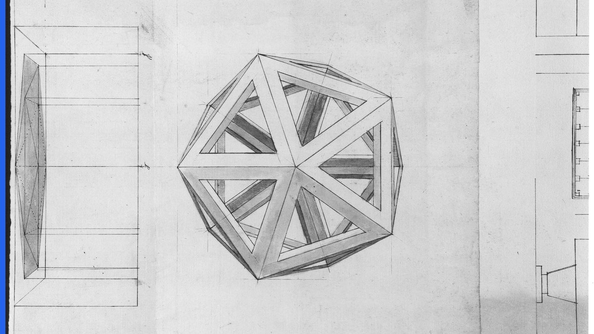
The rule asks for “a sufficient number of views to constitute a complete disclosure of the appearance of the design.” It does not say how many. MPEP 1503.02 fills the gap: the views may include the front, rear, top, bottom and sides, and in practice a conventional complete set is six orthographic views plus at least one perspective view.
Sufficiency is judged against the article, not against a checklist. A design for a flat decal needs fewer views than a design for a hand tool. The test is whether a reader can reconstruct the claimed appearance from what you filed.
Views can be omitted, but only on a narrow condition that is the load-bearing part of the allowance. Under MPEP 1503.02, a view may be left out where it is merely duplicative of another view, or where the surface is flat and carries no surface ornamentation – and the specification says so explicitly. Omit a view silently and you have an incomplete disclosure. Omit it with a statement such as “the bottom of the article is flat and unornamented” and you have a complete one.
The consequence of getting this wrong is not a formality objection. Where inconsistencies between views are of such magnitude that the overall appearance of the design is unclear, the examiner rejects the claim under 35 U.S.C. 112(a) and (b) as non-enabling and indefinite. That is a substantive rejection on the merits of the only claim you have.
So the discipline is to reconcile the views before filing. Every edge visible in the front view must appear where the side views say it should; a chamfer shown in perspective must be present in the orthographic set. Inconsistency between figures is the single most common reason a design application stalls.
Rule 3: Surface Shading Should Be Used – But Is Not Required
The second sentence of the rule says appropriate and adequate surface shading “should be used to show the character or contour of the surfaces represented.” Should, not must – and MPEP 1503.02 confirms that surface shading is not strictly required.
That is a genuine choice, not a loophole, and it cuts both ways. Shading communicates three-dimensional contour that line work alone cannot, and without it an examiner may be unable to tell a domed surface from a flat one – which pushes you straight back into the indefiniteness problem from Rule 2. Where the article has curvature, shading is effectively mandatory in substance even though it is permissive in form.
Two conventions are worth knowing. Oblique line shading must be used to show transparent, translucent and highly polished or reflective surfaces, such as a mirror – that is how you distinguish glass from an open aperture. And shading is never applied to broken-line matter: unclaimed environment is drawn in broken lines and left unshaded, because shading it would suggest you are claiming its contour.
Rule 4: Solid Black Is Barred Except for Black and Contrast
The third sentence is an absolute prohibition with a narrow carve-out: solid black surface shading is not permitted except when used to represent the colour black, or to show colour contrast.
The reason is legibility. A solid black region reproduces as an undifferentiated mass, so contour information is lost and the disclosure becomes ambiguous. But if the article genuinely is black, or if the design depends on a contrast between a dark region and a light one, solid black is the honest way to show it – and the rule permits exactly that.
The practical trap is using solid black as a shortcut for a dark grey or a deeply shadowed recess. That is shading, not colour, and it draws an objection. Use conventional line or stipple shading for contour and reserve solid black for actual black and actual contrast.
Rule 5: Broken Lines Show Environment, Never Hidden Planes
Broken lines do two jobs in design practice. They show visible environmental structure – the thing the design sits in or on, which you are not claiming – and they mark the boundary of a claimed portion within a larger article. The fourth sentence of the rule permits the first use and forbids a third one: broken lines may not be used to show hidden planes and surfaces that cannot be seen through opaque materials.
In utility drawings, broken lines routinely indicate hidden internal structure. Carry that habit into a design case and the drawing becomes ambiguous, because the reader cannot tell whether a broken line means “unclaimed” or “concealed.” If you need to show an interior, use a sectional view instead.
Three drafting conventions keep broken lines out of trouble. They must not be heavier than the lines of the claimed design. They should not cross or intrude on the claimed design where that can be avoided. And the specification must explain their purpose, so the scope of the claim is unambiguous.
Boundary lines carry a priority consequence worth flagging. In In re Owens, 710 F.3d 1362 (Fed. Cir. 2013), the Federal Circuit held that an unclaimed boundary line drawn in a continuation keeps its 35 U.S.C. 120 priority only if it makes explicit a boundary that was already present – though unclaimed – in the original disclosure. You cannot carve a new sub-design out of an old drawing and keep the old date.
Rule 6: No Alternate Positions, No Mixed Media
Three of the seven sentences police how the figures are produced, and they are the easiest to comply with once you know they exist.
Alternate positions. Illustrating alternate positions of a design component with full and broken lines in the same view is not permitted. A hinged lid shown both open and closed in one figure describes two appearances, and the single design claim can only point at one. Use separate figures and say in the specification that they show the same design in different positions.
Mixed media. Photographs and ink drawings may not be combined as formal drawings in one application. It is one medium or the other for the whole disclosure, which matters when a client sends three clean renders and one photograph of a prototype.
Photographs. Under 1.84(b), photographs – including photocopies of photographs – are not ordinarily permitted in utility or design applications; they are accepted where they are the only practicable medium, which in design practice means an ornamental effect that line work cannot capture. Where photographs are used in lieu of ink drawings, the rule adds a restriction of its own: they must not disclose environmental structure and must be limited to the design claimed for the article. A photograph showing the article on a desk, with the desk visible, fails that test – and unlike a drawing, you cannot simply convert the background to broken lines.
Rule 7: Colour Needs No Petition in a Design Case
This is the asymmetry that catches practitioners crossing over from utility work. Under 37 CFR 1.84(a)(2), colour drawings are permitted in design applications outright. There is no petition and no petition fee.
A utility application is the opposite. Colour is accepted there only after the Office grants a petition under 1.84(a)(2) accompanied by the fee set in 37 CFR 1.17(h), together with the required number of sets – one if filed through the USPTO patent electronic filing system, three if not.
Both routes require the prescribed specification statement: “The patent or application file contains at least one drawing executed in color. Copies of this patent or patent application publication with color drawing(s) will be provided by the Office upon request and payment of the necessary fee.” Filing colour figures without that paragraph draws an objection even in a design case where the colour itself was fine.
One more thing follows from colour: if you claim it, you are claiming it. Colour in a design drawing becomes part of the claimed appearance, which narrows scope. Where the colour is incidental to the design, black-and-white line work with conventional shading is usually the stronger filing.
Filing the Same Design Outside the United States
37 CFR 1.152 is a US rule, and the instinct to find its European twin leads people badly astray. Two corrections are needed.
First, European designs are not an EPC matter at all. A registered Community design is filed at the EUIPO, and international design registrations run through the Hague System at WIPO. The European Patent Office does not register designs, so no provision of the EPC governs your design figures.
Second, the provision usually cited for European drawing form no longer exists. Rule 46 EPC – “Form of the drawings” – was deleted with effect from 1 February 2023, together with Rule 49(3) to (12) EPC, as part of the EPO’s digital-transformation package. The form requirements moved into a Decision of the President of the EPO published in the Official Journal, which is why the EPO was then able to begin accepting drawings filed electronically in colour or greyscale from 1 October 2025 without amending the Implementing Regulations. Any checklist still promising “Rule 46 EPC compliance” is citing a rule that has not been in force for nearly three years – and citing it for designs compounds the error.
Note also that the PCT was not changed by any of this. For international patent applications, PCT Rule 11.13(a) still requires drawings in durable black lines “without colorings.” Design filings never touch the PCT, which covers patents only.
The practical upshot for a design portfolio: prepare one master figure set that satisfies 37 CFR 1.152 and 1.84, then adapt it to the Hague System’s own reproduction requirements for the international filing. The US rules are the strictest on surface shading and broken lines, so a set built to clear them travels well.
A Pre-Filing Check That Catches Most Rejections
Run this before the figures leave your desk. It maps one-to-one onto the sentences of the rule, which is the point:
- Sheet size, margins, line weight and figure labels conform to 1.84(f), (g), (l) and (p).
- Every surface of the article is disclosed by some view, or its absence is explained in the specification as duplicative or as flat and unornamented.
- The views are mutually consistent – every edge, chamfer and aperture appears in each view that should show it.
- Surface shading shows contour wherever the article is curved; oblique line shading marks transparent or reflective surfaces; no shading appears on broken-line matter.
- Solid black appears only to represent the colour black or colour contrast, never as a substitute for shading.
- Broken lines show only unclaimed environment or a claim boundary – never hidden internal structure – and are lighter than the claimed lines, with their purpose stated in the specification.
- No figure shows alternate positions in full and broken lines together.
- The disclosure is entirely drawings or entirely photographs, and any photographs show the claimed article alone with no environmental structure.
- If colour is used, the prescribed specification statement is present; confirm you intend colour to be part of the claim.
Our detailed walkthroughs of the individual requirements go deeper on several of these: see our guide to design patent drawing requirements, the dedicated treatment of design patent drawing broken lines, and the companion piece on 37 CFR 1.84 patent drawing standards for the general rule this one builds on. If photographs are on the table, start with photographs in patent applications; for an international design filing, see Hague System design drawings.
Primary sources are worth keeping to hand rather than working from summaries: the regulation itself at Cornell LII, and the Office’s own application guidance in MPEP 1503.02.
Need a Design Figure Set That Clears Examination?
PerspireIP prepares design patent figure sets to 37 CFR 1.152 and 1.84 – full orthographic and perspective view sets, correct surface and oblique line shading, properly weighted broken lines, and the specification statements that go with omitted views and colour drawings. We also adapt the same set for Hague System and EUIPO filings. See our patent drawing services or talk to our drawing team about your design application.
Frequently Asked Questions
How many views does 37 CFR 1.152 require?
The rule sets no number – it requires “a sufficient number of views to constitute a complete disclosure of the appearance of the design.” MPEP 1503.02 contemplates front, rear, top, bottom and side views, and a conventional complete set is six orthographic views plus a perspective view. Sufficiency is judged against the article.
Is surface shading mandatory in a design patent drawing?
No. 37 CFR 1.152 says shading “should” be used, and MPEP 1503.02 confirms it is not strictly required. In practice, an article with curved surfaces needs shading anyway, because without it an examiner may not be able to determine contour – which risks a 35 U.S.C. 112 rejection for indefiniteness.
Can I omit a view of my design?
Yes, but only where the view is merely duplicative of another, or the surface is flat and has no surface ornamentation – and the specification states this explicitly. The statement is what makes the disclosure complete; omitting a view silently does not.
Do design patent drawings in colour need a petition?
No. Under 37 CFR 1.84(a)(2) colour drawings are permitted in design applications without a petition or fee. A utility application needs a granted petition plus the fee under 37 CFR 1.17(h). Both require the prescribed specification statement about colour drawings.
Can broken lines show hidden internal structure in a design drawing?
No. 37 CFR 1.152 permits broken lines for visible environmental structure but bars them from showing hidden planes and surfaces that cannot be seen through opaque materials. Use a sectional view if an interior must be disclosed.
Does Rule 46 EPC apply to design drawings?
No, on two counts. European designs are filed at the EUIPO or through the Hague System, not under the EPC. And Rule 46 EPC was deleted with effect from 1 February 2023; EPO drawing form requirements now sit in a Decision of the President of the EPO.