Table of Contents
An electrical figure set rarely gets objected to because the lines are too thin. It gets objected to because the draftsperson used a symbol the specification never identifies, or crammed signal names into a block diagram that the rules treat as a drawing rather than text. Patent drawings for electrical circuits are judged against provisions drafted with gears and linkages in mind, and three of those provisions behave in ways most engineering teams have never read. Here are seven checks worth running before a schematic reaches a filing receipt.
Why Patent Drawings for Electrical Circuits Draw Objections
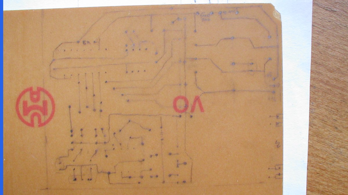
A circuit is not a machine with visible contours, and that single fact drives most of the formalities trouble. There is nothing to shade, no assembly order to explode, and no sectional view worth cutting. What a schematic carries instead is notation — standardised symbols, net labels, pin names, signal designations — and notation is exactly what the drawing rules ration most tightly.
The three recurring failure modes are consistent across the US, European and PCT routes:
- Symbols used without the specification identifying what they represent.
- Text matter on the sheet that exceeds the short catchwords the rules permit.
- Waveform figures split across separate figures instead of sharing one axis.
None of these are aesthetic complaints. Each maps to a specific provision, and each is cheap to fix before filing and tedious to fix afterwards, because a corrected sheet filed later has to be checked for new matter. Our wider guidance on patent diagrams for flowcharts and waveforms covers the diagram side; this piece is about schematics proper.
Check 1: 37 CFR 1.84(n) Permits Symbols Only If the Specification Identifies Them
This is the provision that catches the most circuit filings, and it is two sentences long. 37 CFR 1.84(n) reads: “Graphical drawing symbols may be used for conventional elements when appropriate. The elements for which such symbols and labeled representations are used must be adequately identified in the specification.”
Read the second sentence again. The permission to use a resistor, op-amp or logic-gate symbol is conditional. If the schematic shows a symbol and the description never says what it is, the drawing is not compliant — however standard the symbol is in the trade. IEEE or IEC provenance does not discharge the obligation; the specification has to do it.
In practice that means the description should walk the figure and name each symbolised element at least once, tied to its reference character. A single sentence per block is usually enough: “Amplifier 212 is a differential amplifier.” What fails is a description that discusses function at a high level and leaves the reader to infer the parts from the symbols.
- Inventory every distinct symbol on every sheet before filing.
- Confirm each one is named in the description, not only labelled on the sheet.
- Treat custom or house symbols as needing more explanation, not less.
Check 2: Waveforms Share One Figure and One Axis
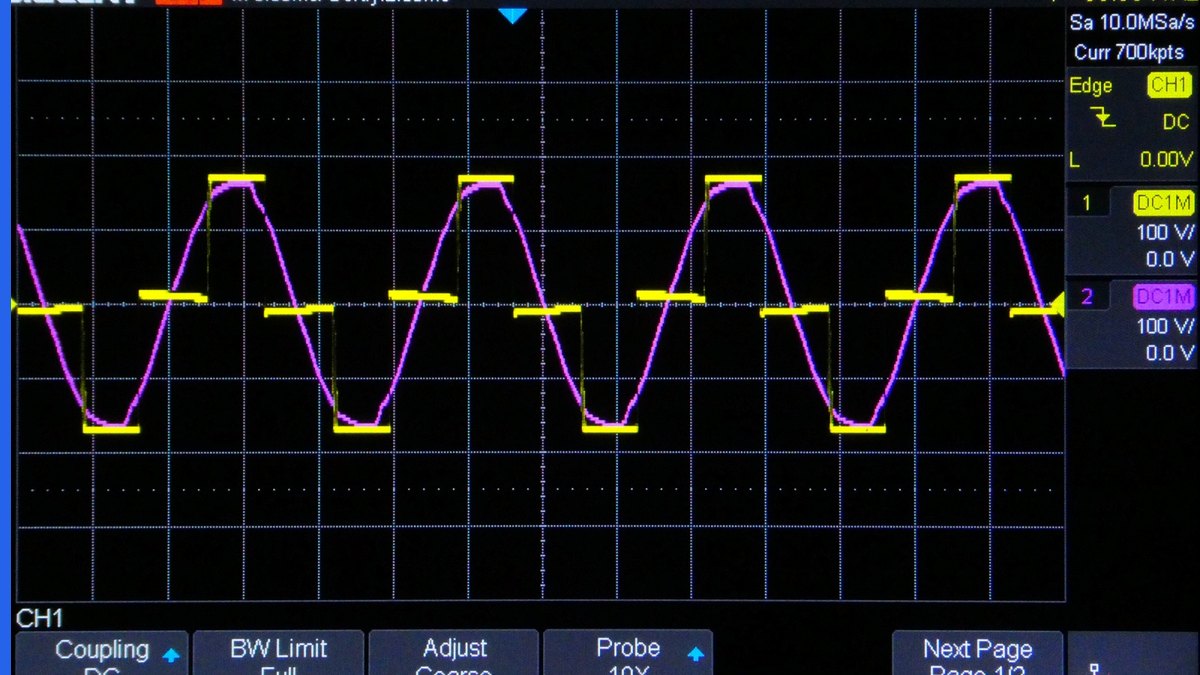
Waveforms are admissible as drawings. 37 CFR 1.84(d) provides that “chemical or mathematical formulae, tables, and waveforms may be submitted as drawings, and are subject to the same requirements as drawings.” The constraint that follows is the one teams miss: a group of waveforms must be “presented as a single figure, using a common vertical axis with time extending along the horizontal axis.”
So a timing diagram showing clock, enable and data cannot be delivered as FIG. 4A, FIG. 4B and FIG. 4C stacked on separate sheets. They belong in one figure, on one axis, where their relative timing is legible. That is the whole point of the rule — timing relationships are the technical content, and splitting the traces destroys them.
There is a matching permission that is genuinely useful and almost never used: 37 CFR 1.84(h) states that “waveforms of electrical signals may be connected by dashed lines to show the relative timing of the waveforms.” Dashed guide lines between a rising edge and the response it triggers are expressly allowed. Most teams avoid them for fear of an objection; the rule invites them.
Check 3: Block Diagrams Are Drawings, So Text Is Rationed
A block diagram looks like a document with boxes. The rules treat it as a drawing, which means the words inside the boxes are text matter on a drawing sheet — and text matter is restricted.
The PCT states the limit most explicitly. PCT Rule 11.11(a) provides that drawings “shall not contain text matter, except a single word or words, when absolutely indispensable, such as ‘water,’ ‘steam,’ ‘open,’ ‘closed,’ ‘section on AB,’ and, in the case of electric circuits and block schematic or flow sheet diagrams, a few short catchwords indispensable for understanding.”
That clause is a carve-out written for exactly this subject matter: circuits and block schematics get a few short catchwords. “Catchwords” is doing real work — “MEMORY CONTROLLER” qualifies, a two-line description of what the controller does does not. The European Patent Office applies the same allowance through Part A, Chapter IX of its Guidelines for Examination, which also asks that a space free of drawing lines be left around any indispensable text so a translation can be dropped in later.
The practical consequence for anyone filing internationally: build the block diagram to the catchword limit from the start. A schematic that passes in one office with paragraph-length labels will need redrawing for the PCT, and redrawing after filing raises the added-matter question discussed below. The same discipline applies to patent drawings for software inventions, where flowchart text is the usual offender.
Check 4: Every Claimed Element Needs a Reference Character
37 CFR 1.83(a) requires the drawing to show every feature of the invention specified in the claims. On a circuit this is easy to fail quietly, because claims are often written in functional language — “a feedback path configured to…” — and the schematic shows nets rather than labelled blocks. If the claim recites a feedback path, something on the sheet has to be identifiable as that path.
The mechanics of labelling sit in 37 CFR 1.84(p). Reference characters “must be plain and legible, and must not be used in association with brackets or inverted commas, or enclosed within outlines, e.g., encircled” — 1.84(p)(1). The circled-reference habit that many CAD tools apply by default is therefore a defect, and it is a common one on exported schematics.
Size is specified too: 1.84(p)(3) requires numbers, letters and reference characters to measure “at least .32 cm. (1/8 inch) in height.” A schematic exported at sheet scale from a tool that sized text for A3 will often drop below that once reduced to a drawing sheet. Our note on patent drawing reference numerals works through the numbering conventions in detail.
- Map each claim element to a reference character before the figures are final.
- Strip circles, brackets and quotation marks from reference characters.
- Check character height after reduction, not in the CAD viewport.
Check 5: Legends Are Permitted, Not Guaranteed
Engineers often want a legend mapping symbols to part types. 37 CFR 1.84(o) allows it, with a condition worth noting: “suitable descriptive legends may be used subject to approval by the Office, or may be required by the examiner where necessary for understanding of the drawing.”
Two things follow. First, a legend is discretionary — it can be objected to, so it should not be the only place a symbol is explained. The specification identification required by 1.84(n) still has to be there independently. Second, an examiner can require a legend, which is a useful outcome to anticipate on a dense multi-sheet schematic: adding one proactively is cheaper than an office action.
Keep legends short enough to stay within the catchword limit on PCT-bound sheets. A full component table is a specification exhibit, not a drawing legend. We cover the distinction in patent drawing legends.
Check 6: At the EPO, Rule 46 EPC No Longer Exists

Most guidance on European circuit drawings still cites Rule 46 EPC, “Form of the drawings.” That rule was deleted with effect from 1 February 2023 (CA/D 10/22, OJ EPO 2022, A101), together with Rule 49(3) to (12) EPC, as part of the EPO’s digital-transformation package.
The requirements did not disappear; they moved. Drawing form is now set by a Decision of the President of the EPO issued under Rule 49(2) EPC, applied through Part A, Chapter IX of the Guidelines for Examination. The practical effect is that presentation rules can change without amending the Implementing Regulations — so a page that cites a rule number from 2022 is not a reliable source, and several competing guides to patent drawings for electrical circuits still do.
That delegation produced a real change quickly. Since 1 October 2025 the EPO accepts drawings filed electronically in colour or greyscale (Decision of the President of 25 July 2025, OJ EPO 2025, A49; Notice, OJ EPO 2025, A57), provided they are contrast-rich and clear at 300 dpi. Drawings only — description, claims and abstract stay black and white. We track the detail in EPO color patent drawings.
Check 7: Colour Will Not Rescue a Dense Schematic
Colour-coding power rails, clock domains or bus widths is standard engineering practice and a poor filing strategy, because the three routes diverge sharply.
- USPTO utility: black and white is normally required (37 CFR 1.84(a)(1)). Colour needs a petition under 1.84(a)(2) with the fee set forth in 37 CFR 1.17(h), one set of colour drawings when filed through the patent electronic filing system (three sets if not), and an amendment inserting the prescribed reference statement into the specification.
- EPO: colour or greyscale accepted on electronic filings since 1 October 2025, contrast-rich at 300 dpi.
- PCT: still black only. Rule 11.13(a) requires drawings “executed in durable, black, sufficiently dense and dark, uniformly thick and well-defined, lines and strokes without colorings.”
A single colour-coded schematic therefore cannot serve all three routes. Worse, a figure whose meaning depends on colour becomes ambiguous the moment it is reproduced in monochrome — and 37 CFR 1.84(l) requires every line to be “durable, clean, black (except for color drawings), sufficiently dense and dark, and uniformly thick and well-defined.” Encode the distinction in line style, line weight or labels, and colour becomes a presentation choice rather than a disclosure dependency.
One caution for Euro-PCT work: adding colour to a figure set after the international filing date is not a neutral formality. If the colour carries information the black-and-white original did not, it invites an Article 123(2) EPC objection for added subject-matter. The PCT drawing requirements should drive the master set.
If the Circuit’s Appearance Is the Point, 1.152 Takes Over
Occasionally the subject matter is how a board or module looks rather than how it works — an ornamental housing, a visible PCB layout, a screen layout. That is a design application, and 37 CFR 1.152 governs the drawings, reversing two habits that are correct in a utility schematic.
Under 1.152, “appropriate and adequate surface shading should be used to show the character or contour of the surfaces represented,” while “solid black surface shading is not permitted except when used to represent the color black as well as color contrast.” Broken lines carry a different meaning again: they “may be used to show visible environmental structure, but may not be used to show hidden planes and surfaces that cannot be seen through opaque materials.” And alternate positions of a design component shown by full and broken lines in the same view are not permitted.
A schematic drawn for a utility filing is therefore not convertible into a design figure set by relabelling it. Our treatment of 37 CFR 1.152 sets out the scope consequences.
A Pre-Filing Checklist for Circuit Figure Sets
Run this before the figures leave your hands. It takes under an hour on a typical set and removes the objections that cost a full response cycle.
- Every symbol on every sheet is identified in the specification (1.84(n)).
- Related waveforms sit in one figure on a common vertical axis, time horizontal (1.84(d)).
- Dashed timing connectors used where they aid understanding (1.84(h)).
- Block-diagram text reduced to short catchwords, with clear space for translation (PCT Rule 11.11(a)).
- Every claimed feature appears on a sheet (1.83(a)) and carries a reference character.
- No circled, bracketed or quoted reference characters; all at least 0.32 cm high (1.84(p)(1), (p)(3)).
- Master set drawn in black line art; colour added only route by route, never as the sole carrier of meaning.
- No European citation that depends on Rule 46 EPC.
Teams filing circuit and chip subject matter together should read this alongside semiconductor patent drawings, where layer representation adds a further set of constraints, and patent drawings for mechanical inventions for the view rules that apply once a circuit sits inside a housing. The underlying provisions are collected in our guide to 37 CFR 1.84.
Have Your Circuit Figures Checked Before You File
PerspireIP prepares and reviews patent drawings for electrical circuits — schematics, block diagrams, timing and waveform figures — against current USPTO, EPO and PCT practice, including the symbol-identification and text-matter rules that cause most objections. See our patent drawing services or talk to us about your figure set before it reaches a filing receipt.
Frequently Asked Questions
Can I use standard IEEE or IEC circuit symbols in a patent drawing?
Yes. 37 CFR 1.84(n) permits graphical drawing symbols for conventional elements. The condition is that the elements represented by those symbols must be adequately identified in the specification — the symbol being an industry standard does not satisfy that requirement on its own.
How much text can a block diagram contain?
Very little. PCT Rule 11.11(a) limits text matter on drawings to a single word or words when absolutely indispensable, and expressly allows electric circuits and block schematic or flow sheet diagrams only “a few short catchwords indispensable for understanding.” The EPO applies the same allowance through Guidelines Part A, Chapter IX.
Do waveforms have to be in the same figure?
A group of related waveforms does. Under 37 CFR 1.84(d) waveforms are submitted as drawings and a waveform group must be presented as a single figure using a common vertical axis with time along the horizontal axis. 1.84(h) also permits dashed lines between waveforms to show relative timing.
Is Rule 46 EPC still the European standard for drawings?
No. Rule 46 EPC was deleted with effect from 1 February 2023 (CA/D 10/22, OJ EPO 2022, A101). Drawing form is now set by a Decision of the President of the EPO under Rule 49(2) EPC and applied through Part A, Chapter IX of the Guidelines for Examination.
Can I file a colour schematic?
It depends on the route. The EPO has accepted colour or greyscale on electronic filings since 1 October 2025. A USPTO utility filing needs a petition under 37 CFR 1.84(a)(2) with the 1.17(h) fee and a specification reference statement. PCT Rule 11.13(a) still requires black lines and strokes without colorings.
What happens if a symbol is not explained in the specification?
Expect a drawing objection and a requirement to amend. The cure is usually an amendment to the description identifying the element, which is normally available because it adds no new matter — but it costs a response cycle that a pre-filing check would have avoided.