
Table of Contents
The numbers scattered across a patent figure look like the least important thing in the application. They are not. A single numeral that appears in the drawings but nowhere in the specification is enough to earn a Notice of Draftsperson’s Patent Drawing Review, and a numeral reused for two different parts can follow you into claim construction years later. Patent drawing reference numerals are governed by their own subsections of 37 CFR 1.84, and those subsections are checked mechanically. This guide walks through the seven rules that decide whether your figures pass, where US and European practice part company, and how to audit a set of drawings before you file.
What Patent Drawing Reference Numerals Actually Do
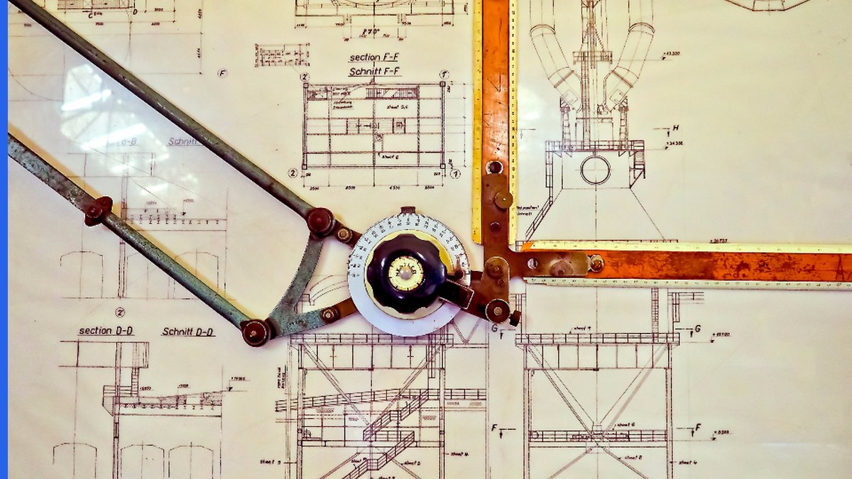
A patent specification and a patent drawing are two descriptions of the same invention in two different languages. Reference characters are the index that joins them. When the description says “the actuator 112 engages the cam surface 118,” an examiner reading that sentence should be able to look at Figure 2 and find 112 and 118 exactly where the sentence says they are. That is the entire job. Everything in 37 CFR 1.84 that touches numerals exists to make that lookup reliable.
This matters beyond formalities. Under 37 CFR 1.83(a), the drawing in a nonprovisional application must show every feature of the invention specified in the claims. If a claim recites a limitation and no figure shows it, you have a drawing objection and, potentially, a written description problem. Patent drawing reference numerals are how you demonstrate that the feature is shown — they are the evidence that the drawing supports the claim rather than merely sitting next to it.
There is a second audience. During prosecution, the examiner uses numerals to map your claim language onto prior art. During litigation, so does everyone else. A numeral that shifts meaning between Figure 3 and Figure 7 gives an opponent a clean argument that the specification is internally inconsistent. The cost of getting this wrong is not a corrected sheet; it is an ambiguity you cannot fix once the application publishes.
The rules below come from 37 CFR 1.84 paragraphs (p) through (u). They are worth reading in the original, because the USPTO’s draftspersons apply them literally.
Rules 1 and 2: The Description and the Drawings Must Agree
The first two rules are the ones that generate most objections, and they are the easiest to break in a long application.
Rule 1 — the two-way consistency rule. 37 CFR 1.84(p)(5) states that reference characters not mentioned in the description shall not appear in the drawings, and reference characters mentioned in the description must appear in the drawings. It runs in both directions. An illustrator who adds a numeral to clarify a figure has created a violation unless the drafter also adds that numeral to the text. A drafter who deletes a paragraph during a rewrite has created one unless the illustrator removes the numeral from the sheet.
Rule 2 — one part, one number. 37 CFR 1.84(p)(4) states that the same part of an invention appearing in more than one view must always be designated by the same reference character, and that the same reference character must never be used to designate different parts. This is the rule that survives the file wrapper. If element 104 is a housing in Figure 1 and a bracket in Figure 5, you have not created a formalities defect so much as a disclosure defect.
Both failures share a cause: drawings and text are usually edited by different people at different times. The practical fix is a numeral table maintained as a single source of truth — number, part name, figures in which it appears — updated whenever either document changes. Applications that skip this step are the ones where a continuation, drafted two years later off the same figures, quietly reuses a numeral.
- Every numeral on a sheet appears at least once in the specification
- Every numeral in the specification appears on at least one sheet
- No numeral names two different parts anywhere in the application
- Numerals carried into a continuation or divisional still match that application’s text
Rules 3 and 4: Size, Placement and Legibility Under 37 CFR 1.84(p)

Rule 3 — the measured minimum. Under 37 CFR 1.84(p)(3), numbers, letters and reference characters must measure at least .32 cm (1/8 inch) in height. This is not a style preference. Patent drawings are reproduced and scanned, and a numeral below the minimum can become unreadable in the published document. CAD exports are the usual culprit: a figure drawn to fit a screen and then scaled down to fit an A4 or letter sheet takes its text down with it.
The same subsection governs placement. Characters should not be placed so as to interfere with comprehension of the drawing, which means they should not cross or mingle with the lines of the figure, and they should not sit on hatched or shaded surfaces. Where a character must indicate a surface or cross-section, 1.84(p)(3) permits it to be underlined, with a blank space left in the hatching or shading so the character reads clearly.
Rule 4 — form and alphabet. 37 CFR 1.84(p)(1) requires reference characters, sheet numbers and view numbers to be plain and legible, and prohibits using them with brackets or inverted commas, or enclosing them within outlines — no circled numerals. They must be oriented the same way as the view, so that a sheet read in the correct orientation reads its labels in the correct orientation too. Under 1.84(p)(2), the English alphabet is used for letters, except where another alphabet is customary, such as Greek letters for angles or wavelengths.
Two conventions are not in the rule but are near-universal in US practice and worth adopting: number parts in even increments so later additions have somewhere to go, and group numerals by figure or by subsystem so a reader can guess roughly where 300-series parts live. Neither is required. Both make the consistency rules above far easier to keep.
Rule 5: Lead Lines and Arrows Are Regulated Too
A numeral floating near a component is not a label. 37 CFR 1.84(q) defines lead lines as the lines between the reference characters and the details referred to, and sets out how they behave: they may be straight or curved, should be as short as possible, must originate in the immediate proximity of the reference character, and must extend to the feature indicated. Lead lines must not cross each other, and they must be executed in the same way as the other lines of the drawing.
The important sentence is the one about when a lead line is required. Under 1.84(q), a lead line is required for each reference character except those which indicate the surface or cross-section on which they are placed — and such a character must be underlined, to make clear that a lead line has not been omitted by mistake. That underline is not decoration. It is the signal to the draftsperson that the missing lead line was deliberate, and its absence is a routine objection.
Arrows have three sanctioned uses under 37 CFR 1.84(r): on a lead line, a freestanding arrow to indicate the entire section toward which it points; on a lead line, an arrow touching a line to indicate the surface shown by that line looking along the direction of the arrow; or to show the direction of movement. An arrow used for anything else — decoration, emphasis, a vague gesture at a region — is outside the rule.
If your figures are dense enough that lead lines are hard to route without crossing, that is usually a sign the figure is doing too much. Splitting it into a general view and a detail view is a better answer than a tangle of curved leads. Our guide to patent drawing views covers when to break a figure apart.
Rule 6: View Numbers Are Not Reference Characters
This distinction is worth stating plainly, because conflating the two produces confusing sheets. Reference characters identify parts of the invention. View numbers identify figures. They live in different namespaces and follow different rules.
37 CFR 1.84(u)(1) requires the different views to be numbered in consecutive Arabic numerals starting with 1, independent of the numbering of the sheets, and, if possible, in the order in which they appear on the sheets. Partial views intended to form one complete view — whether on one sheet or several — are identified by the same number followed by a capital letter, which is why you see Figures 4A, 4B and 4C. View numbers must be preceded by the abbreviation “FIG.”
One provision catches people out: where only a single view is used to illustrate the claimed invention, it must not be numbered, and the abbreviation “FIG.” must not appear at all. A design application or a simple provisional filed with one figure should therefore carry no figure label. Adding “FIG. 1” to a lone view is a defect, not a courtesy.
Because view numbering is independent of sheet numbering, Figure 7 need not sit on sheet 7. Sheet numbers are their own sequence, and mixing the two — labelling sheets to match figures — is a common source of confusion when sheets are later added or replaced. For the full picture on how these subsections fit together, see our breakdown of the USPTO patent drawing requirements under 37 CFR 1.84 and the corresponding MPEP drawing requirements.
Rule 7: Design Applications Follow a Different Logic
37 CFR 1.152 requires that a design be represented by a drawing which complies with the requirements of 37 CFR 1.84, and that the drawing contain a sufficient number of views to constitute a complete disclosure of the appearance of the design. So the character rules of 1.84(p) formally reach design applications. In practice, they almost never bite, because a design application works differently.
A utility specification describes numbered parts and the drawings key to that description. A design application claims the ornamental appearance of an article as shown, and its description is typically a single sentence plus a list of figure descriptions. There is no parts list for numerals to key to. The claim is defined by what the solid lines show.
What does the work in a design case is line type, not numbering. Structure that is not part of the claimed design but is needed to show the environment in which the design is used may be shown in broken lines (MPEP 1503.02). Everything in solid lines is claimed; everything in broken lines is not. That single convention carries the claim scope that reference characters carry in a utility case — which is why disclaimer strategy in design drawings deserves its own analysis, covered in our note on GUI design patent drawings.
One related trap: 37 CFR 1.152 also provides that photographs submitted in lieu of ink drawings in design applications must not disclose environmental structure, but must be limited to the design claimed for the article. A photograph that captures the surroundings cannot be cured with broken lines the way a drawing can.
Reference Signs at the EPO After Rule 46 EPC Was Deleted
European practice calls them reference signs rather than reference characters, and the legal basis moved recently. Rule 46 EPC, which set out the form of the drawings, was deleted with effect from 1 February 2023, as part of the package of amendments the Administrative Council adopted at its 172nd session in October 2022 to support the EPO’s digitalisation programme. If you are citing Rule 46 EPC today for a drawing formality, you are citing a rule that no longer exists.
The requirements did not disappear; they moved. The presentation requirements for application documents now sit in Rule 49 EPC together with a Decision of the President of the EPO, which was intended in the first instance to restate the deleted material rather than change it. Putting the detail in a Presidential decision lets the EPO adjust formatting requirements as its filing systems change without amending the Implementing Regulations — the same mechanism that later allowed the EPO to open the door to colour drawings, which we cover in our piece on EPO colour patent drawings.
The substantive European rule that has no direct US analogue is Rule 43(7) EPC. Where the application contains drawings with reference signs, the technical features in the claims should preferably be followed by those reference signs in parentheses — and the rule states expressly that such reference signs are not to be construed as limiting the claim. US practice does not put numerals in claims as a matter of course, and importing that habit into a US application invites an argument that the claim is limited to the embodiment shown. Keep the two drafting conventions separate.
If your figures are heading to both offices, the practical advice is to design the numbering for the stricter reading: consistent one-part-one-number across every figure, every numeral supported in the text, and no numerals in US claims. That set travels. See our PCT drawing requirements guide for the international-phase overlay.
Primary sources are worth keeping to hand: the current text of 37 CFR 1.84 is published by the USPTO in Appendix R of the MPEP, and the EPC Implementing Regulations are maintained on the EPO’s legal texts site.
A Pre-Filing Reference Numeral Audit That Takes 20 Minutes
Every objection described above is detectable before filing, and none of the checks are difficult. The reason they get skipped is that they happen at the point in a matter where everyone is tired and the deadline is close. Running them as a fixed list removes the judgement call.
- Extract every numeral from the specification and every numeral from the sheets into two lists, then diff them. Anything appearing on one list only is a 1.84(p)(5) violation.
- Sort the combined list by numeral and read down it. Any numeral mapped to two part names is a 1.84(p)(4) violation.
- Measure the smallest character on each sheet at final print scale and confirm it clears .32 cm (1/8 inch).
- Check that no character crosses a line or sits on hatching, and that any character without a lead line is underlined.
- Confirm arrows appear only in the three roles 1.84(r) allows.
- Confirm figures are numbered consecutively from 1, that partial views share a number with letter suffixes, and that a single-view application carries no FIG. label at all.
- For a European filing, confirm any reference signs used in the claims are in parentheses under Rule 43(7) EPC — and confirm none appear in the US claims.
The first two steps are mechanical enough to script, and most drafting teams eventually do. The remainder need a person looking at the sheets at print size, which is the step that CAD workflows tend to skip. Getting patent drawing reference numerals right is not craft; it is bookkeeping performed carefully, and the whole audit costs less than a single round of corrected sheets.
Where numeral errors do slip through, they usually arrive alongside other formalities defects — margins, line weight, view selection. Our review of the most common patent drawing mistakes that trigger office actions sets out what else the draftsperson is looking at on the same pass.
Get Your Drawings Checked Before the Draftsperson Does
PerspireIP’s illustrators prepare and audit figures for US, EP and PCT filings, and consistency checking on patent drawing reference numerals is part of every set we deliver — numerals reconciled against your specification, lead lines and arrows conformed to 37 CFR 1.84, and view numbering checked before the application leaves your office. See our patent drawing services, or contact us with a set of sheets and we will tell you what a draftsperson would flag.
Frequently Asked Questions
Can a reference numeral appear in the drawings but not in the description?
No. 37 CFR 1.84(p)(5) states that reference characters not mentioned in the description shall not appear in the drawings, and that characters mentioned in the description must appear in the drawings. The requirement runs in both directions.
How large must patent drawing reference numerals be?
At least .32 cm (1/8 inch) in height, measured at final sheet scale, under 37 CFR 1.84(p)(3). Characters must also stay clear of the lines of the figure and off hatched or shaded surfaces.
When can a reference character be used without a lead line?
Only where the character indicates the surface or cross-section on which it is placed. 37 CFR 1.84(q) requires that such a character be underlined, so it is clear the lead line was omitted deliberately rather than by mistake.
Do design patent drawings use reference numerals?
In practice, no. 37 CFR 1.152 requires design drawings to comply with 37 CFR 1.84, but a design application has no numbered parts list for characters to key to. Claim scope is carried by line type — solid lines are claimed, broken lines show unclaimed environment.
Is Rule 46 EPC still the basis for European drawing requirements?
No. Rule 46 EPC was deleted with effect from 1 February 2023. The presentation requirements for application documents now sit in Rule 49 EPC together with a Decision of the President of the EPO, which initially restated the deleted provisions.
Should reference signs go inside the claims?
At the EPO, yes — Rule 43(7) EPC says technical features in the claims should preferably be followed by the reference signs in parentheses, and those signs are not construed as limiting. US practice generally does not put numerals in claims, and doing so risks an argument that the claim is limited to the illustrated embodiment.