Table of Contents
Most guides tell you what the rules say. Almost none of them show you what a compliant figure set actually looks like when the invention is a catheter, a switching circuit, a training pipeline or a moulded housing. That gap is why applicants keep filing drawings that satisfy the margin rules and still draw an objection. The patent drawing examples below work the other way round: each one starts from a real filing scenario, sets out what the figures have to contain, names the provision of 37 CFR 1.84 or 1.152 that governs it, and identifies the objection the set is built to avoid. Read them as templates for judgement rather than as clip art.
What Useful Patent Drawing Examples Have in Common
Every figure set that clears examination without a formalities cycle does the same three things. It shows every feature recited in the claims, because 37 CFR 1.83(a) requires the drawing in a nonprovisional application to show every feature of the invention specified in the claims. It uses one reference character per part, consistently, across every view. And it survives reduction, because the drawing will be reproduced smaller than you drew it.
Everything else is scenario-specific, and that is where applicants come unstuck. A flowchart and a sectional view of an injector are both legitimate figures, but they fail examination for entirely different reasons. The useful question is never “what do patent drawings look like” — it is “what does this kind of invention have to show, and under which rule”.
- Sheet format — 21.0 by 29.7 cm (A4) or 21.6 by 27.9 cm, per 37 CFR 1.84(f), with margins of 2.5 cm top, 2.5 cm left, 1.5 cm right and 1.0 cm bottom under 1.84(g)
- Line quality — durable, clean, black, sufficiently dense and dark, uniformly thick and well-defined, under 1.84(l)
- Reference characters — at least 0.32 cm high under 1.84(p)(3), and the same character always used for the same part
- View numbering — consecutive Arabic numerals preceded by “FIG.”, numbered independently of the sheets, under 1.84(u)
- Scale — legible when the drawing is reduced to two-thirds, under 1.84(k)
Those constraints are constant. The eight scenarios below are where the judgement lives.
Example 1: A Mechanical Assembly in Exploded and Sectional Views
The classic case: a multi-part device — a drug-delivery pen, a coupling, a hinge assembly — where the claims recite an internal relationship between parts. A single perspective view cannot carry it, because the parts that matter are inside the housing.
The working set is usually four figures. FIG. 1 gives a perspective view of the assembled device for orientation and for the front page, which 1.84(j) asks you to think about. FIG. 2 is an exploded view under 1.84(h)(1), where the separated parts are embraced by a bracket to show the assembly relationship. FIG. 3 is a sectional view under 1.84(h)(3), taken on a plane marked in FIG. 1 by a line with arrows, with the cut surfaces hatched by regularly spaced oblique parallel lines. FIG. 4 is an enlarged detail of the engagement geometry.
Two objections dominate here. The first is a section plane that appears in the sectional view but was never indicated in the view it was taken from — the reader cannot locate the cut. The second is hatching that runs at the same angle across two adjacent parts, so the interface between them disappears at reduced size. Change the angle or the spacing between adjacent components and the boundary survives.
If you want the full taxonomy of when each view type is required rather than merely permitted, our guide to patent drawing views works through them individually.
Example 2: An Electrical Schematic Built From Graphic Symbols
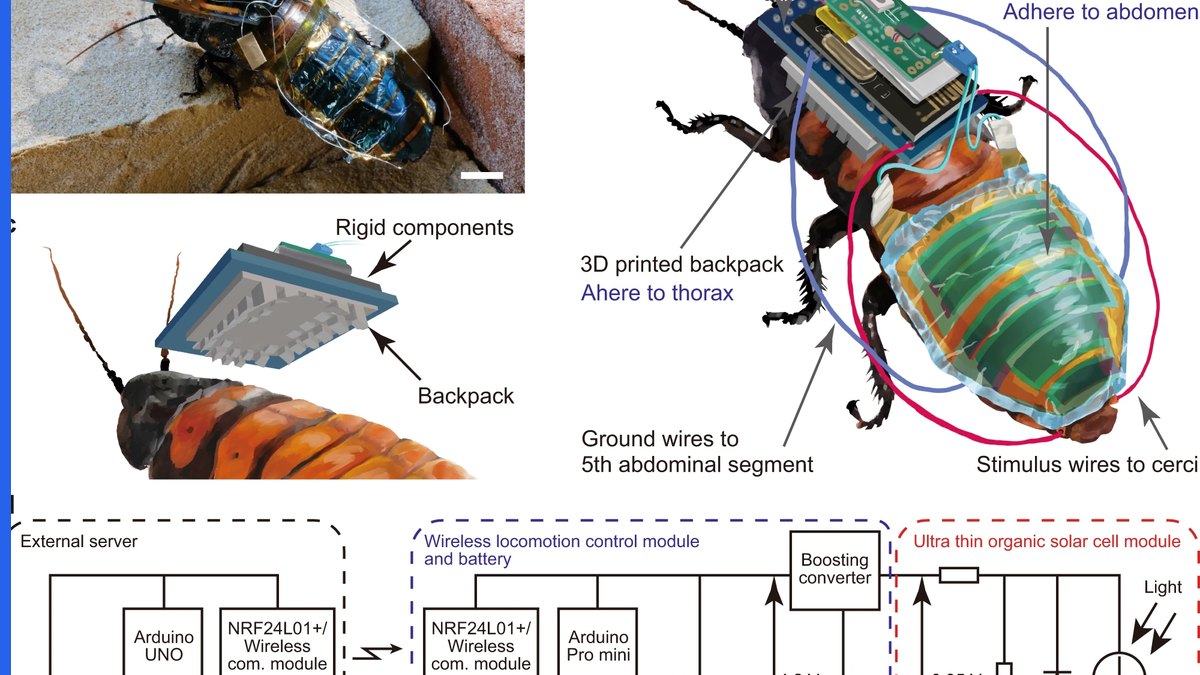
For a power-conversion topology or a sensing front end, drawing every resistor as a physical object would be absurd, and the rules do not ask you to. 37 CFR 1.84(n) permits graphical drawing symbols for conventional elements where appropriate, and the symbol becomes an adequate disclosure of the element it represents.
A competent schematic set separates levels. FIG. 1 is a block diagram of the system, with each block labelled by a short legend under 1.84(o) and given a reference numeral. FIG. 2 expands the block that the claims actually recite into a full schematic with component-level symbols. The mistake is to file only the block diagram when the claims recite the switching arrangement inside one of the blocks — then the claimed feature is nowhere in the figures and 1.83(a) is not satisfied.
Legends carry a second trap. 1.84(o) allows suitable descriptive legends, but asks that they contain as few words as possible, and text on a sheet is not translated when the same application is filed abroad. A block labelled “controller” with numeral 120 travels; a block labelled with a sentence does not.
Non-standard symbols are still allowed, but they must be self-explanatory or explained in the description. If you have invented the component, draw it — do not invent a symbol for it.
Example 3: A Software Flowchart That Carries Real Disclosure
Software and machine-learning filings produce the weakest figure sets we see, and the reason is structural: a flowchart is easy to draw badly and almost impossible to fix later, because the prohibition on new matter is absolute. Whatever the figures disclose on the filing date is the whole of what the application can ever claim.
A defensible set has three layers. FIG. 1 is a system architecture diagram — clients, servers, data stores, the boundaries between them. FIG. 2 is the method flowchart, with each step in its own box, each box numbered, and the numbering scheme matching the description step for step. FIG. 3 is the data structure or the timing relationship that makes the method work: the record layout, the message sequence, the state machine.
The failure mode is the four-box flowchart that reads “receive data — process data — generate output — display result”. It is formally compliant. It discloses nothing, and under 35 U.S.C. 112(a) it will not support a claim amendment when the examiner cites art. Among all the patent drawing examples on this page, this is the one where compliance and adequacy are furthest apart.
We set out what sufficient granularity looks like for computer-implemented inventions in patent drawings for software inventions, including how far to decompose a model architecture before the figures stop earning their keep.
Example 4: Chemical Formulae, Graphs and Waveforms as Figures
Applicants are often surprised that a structural formula is a drawing. It is. 37 CFR 1.84(d) provides that chemical or mathematical formulae, tables and waveforms may be submitted as drawings, subject to the same standards as any other figure.
The practical consequences are specific. Each formula must be labelled as a separate figure, using brackets where necessary to show that information is properly integrated. Waveforms of electrical signals may be connected by dashed lines and presented as a single figure, provided the vertical alignment that gives them meaning is preserved. And every one of them still has to satisfy 1.84(l) on line quality and 1.84(p)(3) on character height — which is where exported spreadsheet charts fail, because axis labels shrink below 0.32 cm and grey gridlines are not black.
For pharmaceutical and biotech sets, the usual repair is to redraw the plot rather than export it: solid black axes, a small number of distinguishable line styles instead of colour, data labels set at a legible height, and the legend moved out of the plot area.
Example 5: Design Patent Figures and the Broken-Line Rule
A design application is the one case where the figures are not evidence of the invention — they are the claim. 37 CFR 1.152 governs design drawings, and it is worth reading in full because it is short and unusually consequential.
The conventional set is seven views: perspective, front, rear, left side, right side, top and bottom. Views may be omitted where they are flat and unornamented, or where a view is a mirror image of one already shown, provided the description says so. Under 1.152 the appearance of the article is shown by appropriate means, including surface shading — and surface shading is what distinguishes an open aperture from a solid recess in a line drawing.
The decision that actually sets scope is line type. Solid lines claim; broken lines disclaim. Drawing the whole product in solid line claims the whole product and gives a competitor an easy design-around by changing any unclaimed feature. Putting the environment and the unclaimed portions in broken line, with a statement in the description explaining that the broken lines form no part of the claimed design, is how scope is deliberately set rather than accidentally conceded.
The rule also prohibits including in one design application more than one embodiment or independent and distinct inventions — a restriction that has no equivalent on the utility side. Our comparison of utility and design patent drawings works through where the two regimes diverge.
Examples 6 and 7: Photographs and Replacement Sheets
Example 6 — photographs. 37 CFR 1.84(b)(1) accepts black and white photographs in utility and design applications where photographs are the only practicable medium for illustrating the claimed invention. That covers electrophoresis gels, blots, autoradiographs, cell cultures, histological tissue cross-sections, crystalline structures and in vivo imaging. Colour photographs are treated under the colour provisions and require a petition in a utility application under 1.84(a)(2), which must establish that colour is the only practicable medium. A photograph of a moulded housing does not qualify, however good the product photography is — it can be drawn, so it must be.
Example 7 — replacement sheets. This is the figure set almost nobody prepares in advance and most applicants eventually need. When drawings are amended, the corrected sheet is filed as a replacement sheet, labelled “Replacement Sheet” in the top margin, containing all of the figures that appeared on the original sheet even where only one of them changed. Annotated sheets showing the changes are submitted where the office requires an explanation of the amendment.
The constraint that governs both is the same: no new matter. A replacement sheet may correct a line, a numeral or a formality. It may not add a feature that was not disclosed on the filing date. If the amendment you need is substantive, the answer is a continuation, not a redraw. Our breakdown of the MPEP drawing requirements covers how the Office handles the amendment mechanics.
Example 8: The Same Figure Set at the EPO and Under the PCT
The eighth scenario is not a new drawing — it is the set you already have, filed in Europe. Most divergences are narrow, and they cluster around text, colour and photographs.
Text is the first. European practice keeps words on the sheet to the minimum indispensable for comprehension, carrying meaning in reference signs instead. That is not merely stylistic: drawings are not translated, so an English legend on a sheet stays English while the claims that reference it are rendered into another language on validation.
Colour is the second, and it changed recently. Since 1 October 2025 the EPO accepts and publishes greyscale and colour drawings, with drawings filed electronically in colour published in colour. There is a citation trap alongside it: Rule 46 EPC, “Form of the drawings”, was deleted with effect from 1 February 2023, and the presentation requirements now sit in a Decision of the President rather than in the Implementing Regulations. A response to a formalities communication that cites Rule 46 EPC is citing a provision that no longer exists. We covered the reform in detail in EPO color patent drawings.
The practical rule for a family that will travel: build the master set to the strictest common denominator, keep it legible in greyscale even where colour is permitted, and derive office-specific variants from it rather than maintaining three divergent sets.
A Pre-Filing Checklist Drawn From These Patent Drawing Examples
Run a set against this list before it leaves your desk. It takes a few minutes and it catches the objections that these eight scenarios have in common.
- Every element recited in an independent claim appears in at least one figure. List the claim elements, tick them off against the numerals. This is 1.83(a) and it is the most common substantive miss.
- Every numeral in the figures appears in the description, and every numeral in the description appears in a figure. Orphaned numerals are the most common formalities objection of all.
- One part, one character, everywhere. Families drawn by different hands over several years break this silently.
- Section planes are indicated in the view they were taken from, with arrows showing the direction of sight.
- Reduce the sheet to two-thirds and read it. Hairlines close up, grey turns to nothing, and 0.3 cm numerals become unreadable.
- Views are numbered consecutively and prefixed “FIG.”, and the numbering still matches the description after any late figure was added.
- Text on the sheet is minimal, so the set survives a foreign filing without rework.
Where a set fails several of these at once — typically an older family being extended into a new jurisdiction — rebuilding the master figures is usually faster and cheaper than patching them. The reference-numeral scheme is the part worth preserving; our guide to patent drawing reference numerals explains why a consistent scheme is the single highest-leverage discipline in a long-lived family.
Need Figures Built to These Standards?
PerspireIP prepares filing-ready figures for USPTO, EPO and PCT applications — utility, design and replacement sheets — from CAD exports, inventor sketches, photographs or an outstanding formalities communication. See our patent drawing services, or contact us with the set you need reviewed and we will tell you whether it needs correcting or redrawing before quoting.
Frequently Asked Questions
Do I have to file drawings with every patent application?
Under 35 U.S.C. 113 a drawing is required where it is necessary for the understanding of the subject matter sought to be patented. In practice that means almost every mechanical, electrical and device application. A pure chemical composition claim may not need one, but 37 CFR 1.83(a) still requires that any feature recited in the claims be shown.
Can I use colour in a US utility patent application?
Only on petition. 37 CFR 1.84(a)(2) requires a petition explaining why colour is the only practicable medium for disclosing the subject matter, together with the fee and the required statement in the brief description of the drawings. Most utility applications do not qualify and should be filed in black ink.
What is the difference between a formal and an informal drawing?
Informal drawings are figures that convey the invention but do not meet every requirement of 37 CFR 1.84 — typical of a provisional filing. Formal drawings comply fully and are what a nonprovisional application needs. The disclosure content of both is fixed on the filing date, so an informal drawing that omits a feature cannot be repaired later.
How many views should a design patent application contain?
Conventionally seven: perspective, front, rear, both sides, top and bottom. Views may be omitted where a surface is flat and unornamented or is a mirror image of a view already shown, provided the description states this. Because the drawings are the claim, omitting a view narrows what is protected.
Can drawings be amended after filing?
Yes, by replacement sheet — labelled as such in the top margin and containing every figure that was on the original sheet. What cannot happen is the addition of new matter. Corrections to lines, numerals and formalities are permitted; adding a feature that was not disclosed on the filing date is not.
Will one figure set work at the USPTO, the EPO and under the PCT?
Usually, if it is built to the strictest common denominator. The divergences are narrow — text on the sheet, colour and photographs. Keeping words on the sheet minimal and the set legible in greyscale lets a single master travel with only derived variants rather than three separately maintained sets.